The Construction Line Edit window ( Modeling & Drawing Editor )

" Finite line " ( Modeling only) is explained with a video ( )

Also see :

page 1 | contents | model > | model -- con lines | objects > | objects -- con lines | top


" Copy " " Paste " " Save " " Load " buttons :

  • You'll find buttons like these at the top of this window. They apply to all user-editable settings that are on this window. Click here for more information.
  • You can " Copy " ( ) the settings on this window, then change the " Construction Line__of " number you are editing using the VCR buttons, then " Paste " ( ) those settings to the newly selected construction line.
  • The " Save " ( ) button saves a "form" file to the form/cons-line folder that is used by your current version of this program. Give the form a name that will help users in other Jobs on your network identify its purpose. " Load " ( ) changes all settings on this window to those settings that are stored in the file that you select.
  • " Paste " and " Load " replace mixed entries to a single field with a single entry. " Copy " and " Save " ignore fields with mixed entries, treating them as if they have no entry or do not exist.

page 1 | contents | model > | model -- con lines | objects > | objects -- con lines | top


------ Settings ------

Finite line: or . This option is for construction lines in Modeling only. Also, it only applies to construction lines that were placed by locating two points. A construction line that has been placed by locating one point and an angle (using ANGL or PERP ) will always be an infinite construction line and cannot be made finite.
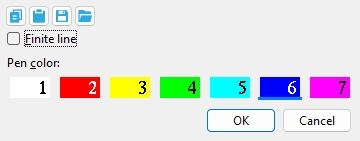
VIDEO When you Construction Line Add Finite using the Locate options ANGL or PERP (which do not locate a point), an infinite construction line is created. The option " Finite line " can make an infinite construction line finite only if the construcition line was originally added by locating two points. (Recorded in SDS2 Detailing , v2015.)

If this box is checked ( ), then the construction line(s) that will be generated when you press " OK " to close this window will be finite. A finite construction line terminates at defined end points.

If the box is not checked ( ), then the construction line(s) that will be generated when you press " OK " to close this window will be infinite. An infinite construction line does not terminate at defined end points, but goes on forever.

Also see: Construction Line Add Finite , Construction Line Add (adds infinite construction lines).

Pen color: White or red or Yellow or Green or Cyan or Blue or Magenta . Press the button for the display color that you want to apply to the construction line. No button is pressed if you are editing multiple construction lines that have different colors.

Since construction lines are not plotted, the choice you make here will not affect the appearance of drawings when they are plotted.

Attached to view ( Drawing Editor only ): A number designating the view that this construction line is attached to. This applies mainly to member details . For instance, a column detail may have a view of face A, face B and face C. It may also have various section views (Section A-A, Section B-B, Section C-C). All graphical objects that are in a particular view are assigned the same number. The only other type of drawing on which you might find multiple views is a submaterial detail .

Assigning the correct number to an object (line, weld symbol, label, etc.), prevents Shorten and Unshorten problems on submaterial details and member details . Automatically detailed submaterial details and member details are the two Drawing Editor drawing types that can have multiple views.


To show a view's number, you can add the X-Y-Z Display to your toolbar. An alternative decoration you can add to display view numbers is the X-Y Dual Show/True Display .

In the Drawing Editor , the X-Y-Z Display shows the view number that the point location target ( ) is over.

Troubleshooting: If you Unshorten a drawing then Shorten , only to find that objects are repositioned in a way that seems wrong, the problem might be that the objects are attached to a view that is not the view that they should be attached to. A good troubleshooting method is to select all of the objects that you believe should be attached to the same view, then right-click ( Menu ) and choose " Edit " on the menu . This will open the Multi-Items Edit window. Look at the " Attached to view " field on that window. If that field is gray (shows no view number), then that field has a mixed entry , indicating that objects in your selection have have two or more different view numbers. Entering the desired view number to the " Attached to view " multi-edit field assigns all objects in your selection that one view number.

View number assignment is fairly random. While view numbers assigned during auto detailing are generally the same as the numbers assigned to views in member isolation (or material isolation's edit views mode ), there are cases where that general one-to-one correspondence will not hold. Also, while the main view of a member detail is almost always view 0, the other views are assigned numbers as they are added, and since the order in which views are added is arbitrary, there is little correspondence between a view's number and its type.

How can objects be assigned wrong view numbers? When a user adds an object to a drawing on which there are multiple views (a member detail or a submaterial detail), it is the responsibility of that user to ensure that the object is attached to the correct view. That sounds like an easy thing to do, but it isn't always so simple. Take, for example, a pointer . When a user adds a pointer using Objects > Pointers > Add , the user does not see the Pointer Edit window and therefore does not see the " Attached to view " entry field. Pointers can also be added using Paste , Paste at Original Location , Paste Repeatedly , Paste Special , Paste to Several , Add Standard Detail , Add Standard Detail to Several , Add Weld Combo , Hole Sym Combo , Label Combo , etc. Each of these tools is a different way for users to add a pointer to a wrong view.

Layer ( Drawing Editor only ):

Select the drawing layer (any layer given a " Name ") that you want the construction line you are adding or editing to be drawn on after you press " OK " to close this window. If that layer happens to be hidden (not marked " Show "), the construction line will disappear after the first Redraw .

page 1 | contents | model > | model -- con lines | objects > | objects -- con lines | top


For Edit Construction Line in the Drawing Editor only :

Construction Line _ of __ ( Drawing Editor only -- not applicable to Add or multiple edit ): The identification number of the construction lines you are editing and the total count of construction lines in your current drawing. You can use the VCR buttons to select a different construction line and edit that construction line while still on this window. When a construction line on a shown layer is selected, it is displayed in green (cyan if its actual color is green). The selected construction line must be on a shown layer for it to be shown.

VCR buttons (first-previous-next-last) for selecting a construction line to edit.

Note: If you change one construction line, then select a different construction line, the first construction line remains changed even if you press " Cancel " on this window.

page 1 | contents | model > | model -- con lines | objects > | objects -- con lines | top


To close this window :


"OK" (or the Enter key) closes this window and completes the Construction Line Add or Construction Line Edit operation.

Defaults: When you press " OK ," the settings on this window -- except mixed entries -- become the default settings for the next construction line you Add during this session of the Drawing Editor . Even if all you do is double-click a construction line and press " OK " without making any changes on this window, this window's settings become the defaults for the next-added construction line. The settings on this window do not become the defaults for new construction lines if you press " Cancel " to close this window (unless you used the " Construction Line _ of __ " widget).

"Cancel" (or the Esc key or the button) closes this window without saving any of the changes you have made. " Cancel " only cancels the changes made to the construction line whose number is currently selected in the " Construction Line _ of __ " widget.

Tip 1: Although " Cancel " does not cancel changes made to construction lines previously edited on this window, Undo does undo all those changes.

Tip 2: If you double-click a construction line just to review it and don't want to set the defaults for to-be-added construction lines, the best way to close this window is to press " Cancel. "

page 1 | contents | model > | model -- con lines | objects > | objects -- con lines | top